Links
Tags
Building a Synchronised Christmas Lights to Music Display - Part 1
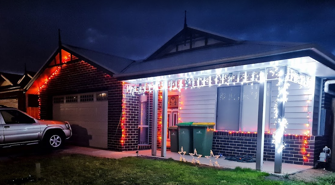
With only a couple more lockdowns to Christmas, it's time to get those gifts ready, plans organised and all that other stuff people do in the leadup. I used to despise people who'd start this far out from Christmas, but this year is a little different. My son last year (who is coincidently 1 year old today!) was mesmorised by some Christmas lights we put on the outside of our house last year. Nothing fancy - just some icicles and fairy lights from good ol' Bunnings. They did the blinky blink thing and he really enjoyed it.
No surprises that Covid-19 lockdowns have done a number on people looking for inspiration and last year it really shone through at least where I live with the sheer number of displays up compared to previous years. Some are quite impressive - entire houses covered in more fairy lights that would give Griswald a run for it's money. I'm also reminded of a display I saw a few years ago in the western part of Victoria that seemed to have some crazy Dubstep tunes pumping out to Christmas Lights. While it's not my choice of music, I can appreciate the effort that went into synchronising Arches to the bouncing beats.
I've always wanted to build a full-on Christmas display. I figure that with some programming talent, recent work on 3D printing and a few Raspberry Pi's and Arduinos, I should be able to build something similar albeit without all the Dubstep. Perhaps something a little more traditional and banter-ish.
Amazon sneakily recommended me some WS2811 lights and to make matters worse for me, they sealed the deal with a $5 coupon to go with it 😊. I figured at the very least I can start experimenting with a Raspberry Pi and turning these "NeoPixels" on and off individually.
In the meantime, I put my Google-Fu to good use and found some displays which looked interesting nearby but nothing out where I live in the eastern part of Victoria. I found the one in the western part of the state that I saw as well as another that had a large Mega Tree. There's just something not quite right to me though - don't get me wrong, it's a perfectly good display but not something that I could really see fitting my front yard.
That lead me to another forum (yes - active forums still exist apparently!) AusChristmasLighting. I must have spent 3, 4 maybe even 5 hours working through the Display Videos section - there were some pretty awesome synchronised displays there. With some YouTube-Fu, a guy by the name of Tom BetGeorge kept coming up and I eventually found the display and song that would inspire me now to build some props and try something simple. The music sequencing is near perfect in time to music, the banter the Trees have is fantastic - this is the sort of thing I'd been wanting to do for a while. It's amusing, kid friendly and has the right amount of joy for me that would make it worth doing.
The forum I mentioned earlier - at first I didn't know it was an active forum until I started looking through the comments section of those videos. Definitely a treasure-trove full of advice (conflicting sometimes, but at least you get to hear lots of different opinions as this can get expensive very quickly if you make a mistake). The one consistent theme was a lot of praise for some free software written by an Aussie called xLights. On face value, it's sequencing is inspired by interfaces similar to FL Studio which I use a lot for sequencing music, and thought I'd jump right in and mock up a layout - see what this thing could do. It was fairly intuitive I've got to say. It doesn't look well organised when you first load it up on a 4K screen, but I was able to, having not read any manuals or watched any YouTube videos, roughly work out what to do. So much so that I had created my first rough layout.
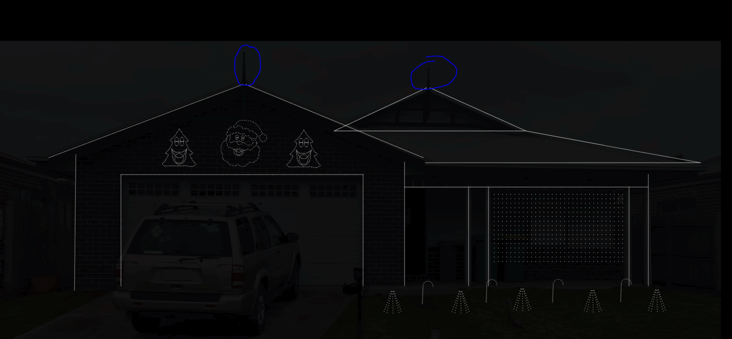
Those Christmas Trees and Santa were part of what I would find out later to be a supplier of 'Coroplast' Christmas Props. I did have to wonder what kind of rock I'd been under to not realise this stuff was readily available but unfortunately shipping would prove to be a bit much and the sizing would not be compatible under the roof line - given the decorative elements already there.
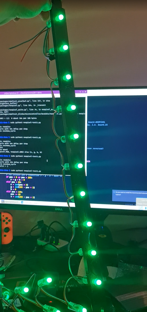
Those lights I ordered eventually arrived so I started sketching up a template that should fit the bulbs. The best way I find to work with 3D printing, especially when it comes to measuring up things is to take a measurement, but then put a hole slightly bigger in as well. Print a few test templates. I wrote a few lines of code using a Python library for WS2811 LEDs.
Great! The next step would be to climb up the side of the house and on the roof to get some measurements and think about custom designing some of these props. They would need to have a particular wiring order (configurable in xLights) and an appropriate size. Having drawn half a tree in Sketchup, I eyeballed the placement of the correct dimension for those bullet pixels. Once done, it was copied and flipped horizontally for symmetry and I began drawing Jigsaw lines in (I had experimented with a couple of joining techniques, this one works well for ABS at least. As you can tell, this isn't going to leave much room for error, but nothing a Mallet can't solve.
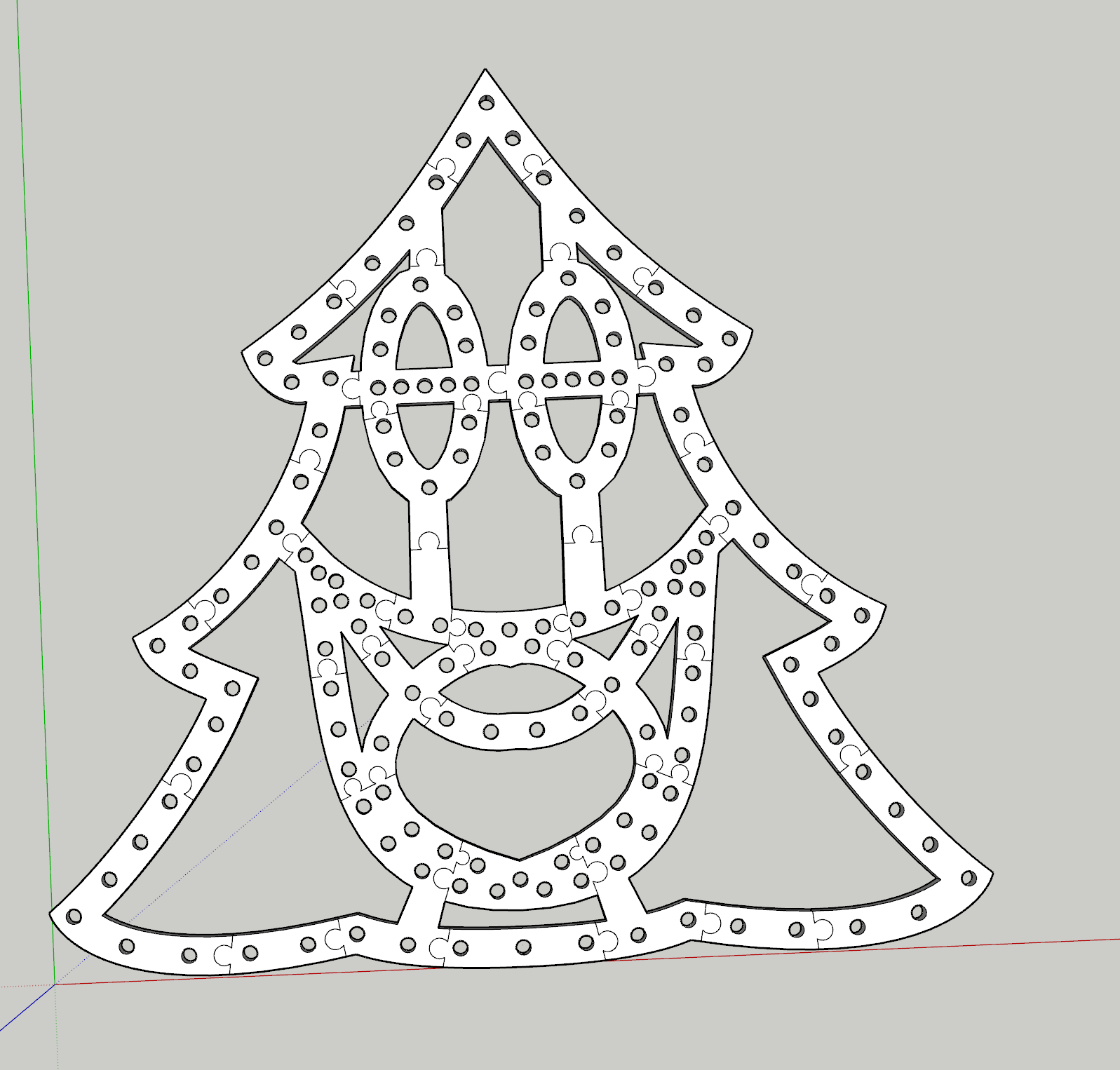
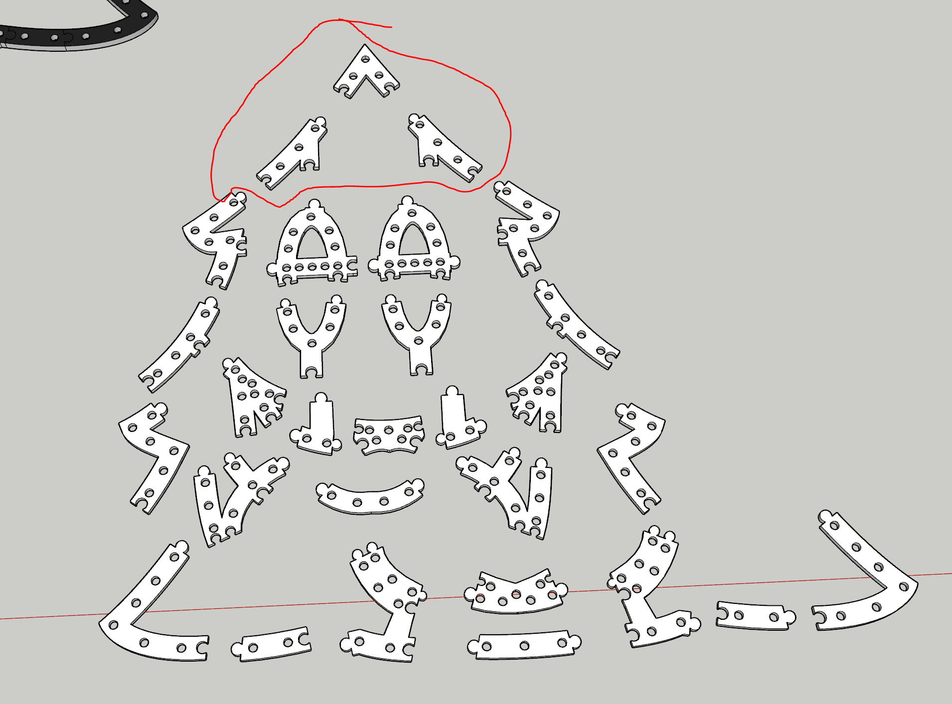
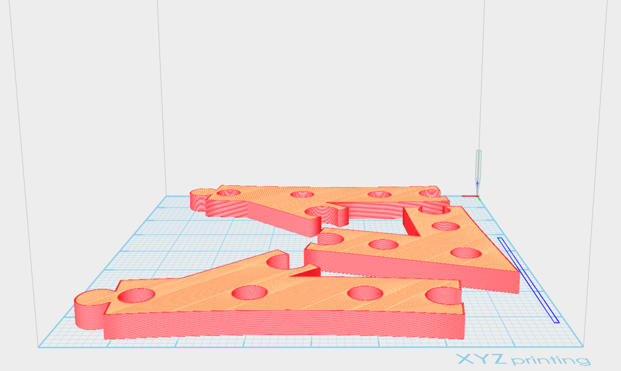
The print time would take around 5 days to complete. This method isn't perfect by any means. As it turns out, either the print diameter or the bulbs themselves are not identical meaning some fit well, some are too loose and some are too tight. Also, the eye balling of bullet placement should have taken into consideration strings of 50 to avoid lots of cutting, splicing and soldering. If I were to do this again, I'd probably more densely pack pixels and perhaps shape up more of a mouth to get it to 200 pixels and look to more evenly space the pixels including changing the hole design so the bulbs "clip" in rather than hard pressed. So while not perfect, the dimensions will certainly fit within the desired space.
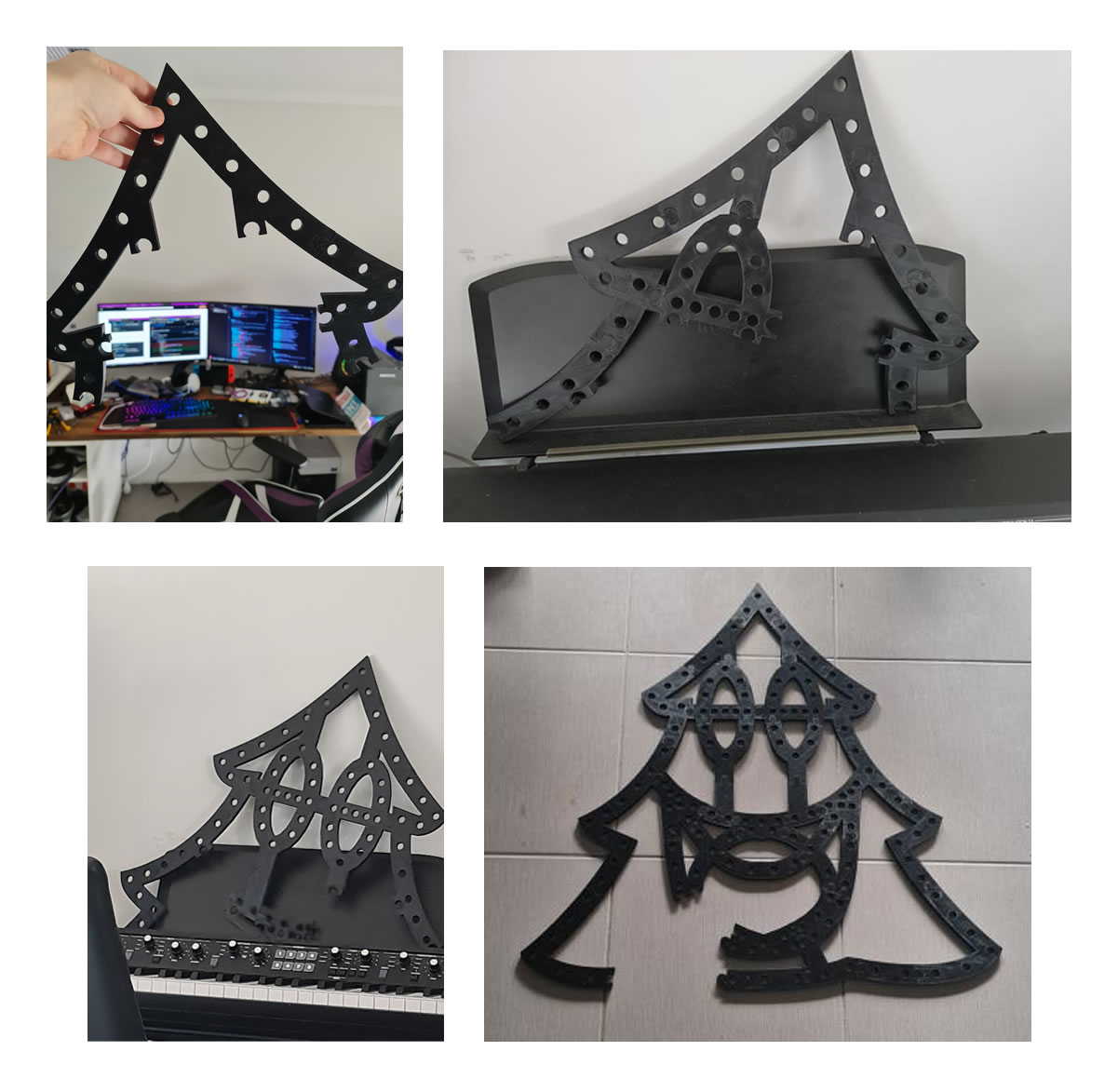
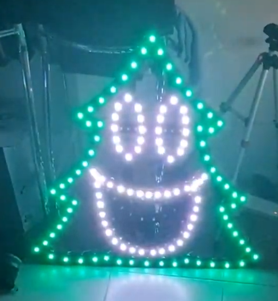
With all the bulbs pushed in using a tool from this guy (which I should have found before I started, it would have saved my hands a significant number of cuts not too dissimilar to 90s era PCs), it was time to fire up xLights, and an OS for the Raspberry Pi called Falcon Player. Having connected the 12V string of 156 bulbs to the Raspberry Pi and injecting some 12V 5A into the string, and a face singing a song, well... here is the result (albeit with a bulb or two that requires better remapping).
There has been a lot of progress in the last few weeks on this including the Mini Tree, Santa and Candy Cane. I'm still yet to determine how i'll complete a Matrix, but I've got some ideas using some PVC Conduit and some 3D Printed templates to drill in. I'm also waiting on some WS2812B LED Strips to come in from AliExpress to do the house outline with. I've also sequenced a couple of songs already to get the hang of xLights (hint: there are a tonne of YouTube videos explaining concepts to help you accelerate your way to creating effects). Those will certainly be a bit of fun to work with when the time comes, but none the less this year's Christmas display is shaping up to be something awesome.
Building a Raspberry Pi mini rack - Part 1
Earlier this year, I managed to amass a table top full of electronics. Arduino's, Raspberry Pi's, Breadboards and components - you name it, it was covering my desk. Most of that is now packed in drawers thanks to the 3D Printing workbench I built last weekend. With a growing number of projects requiring GPIOs or just brushing up on my Kubernetes skills, I need a way to logically organise my growing collection of Raspberry Pi 4's such that they are all usable and clustered for some upcoming projects.
The obvious choice was to build a mini rack that can stack neatly on the table while doing some development work. Each Raspberry Pi would need some way to quickly identify what's going on (via an OLED screen) and ideally a few LED lights for some general purpose identification work. This rack would need it's own power and networking, ideally with the capability to add a Mobile Internet (USB) or Wireless capability for any portable or outdoor use. With this in mind, the part list is below.
- 1 x Anker 60W USB Charger - This device looks great on paper and should comfortably run 3 x Raspberry Pi 4's with it's 15W draw at full load.
- 3 x Raspberry Pi 4's - The brains of the operation - while there are plenty of limits on the cheaper Pico's and Zero's, these don't tend to have restrictions so you can find them around fairly easily. I've opted for 8GB ones to add extra room for database containers.
- 1 x TP-Link AC750 - This ended up a difficult choice. The location of the Ethernet Port and Switch sold me on this one, the USB cable for Mobile Internet can be accessed on the side so this is a bit easier to get to than some of the other more capable GL.Net devices. The lack of an extra Ethernet port for WAN is a downer, but given it's only to provide internet connectivity to the cluster, the Wireless capability will have to do. It's also compatible with DDWRT so if I find myself stuck, there are a few hacks that might help this out.
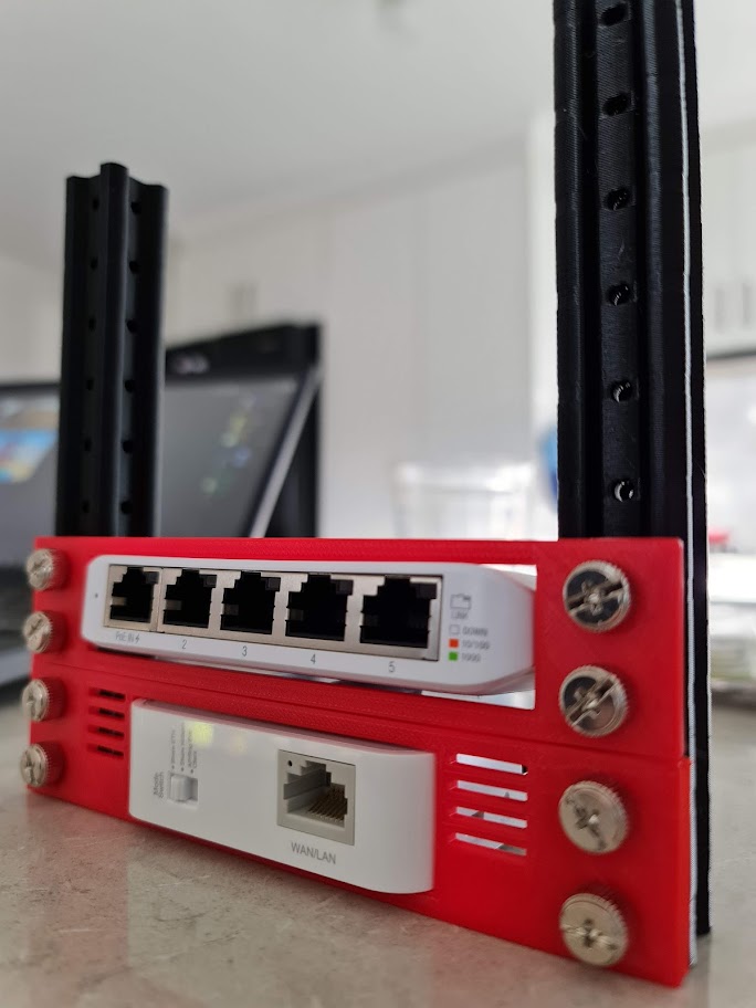
- 1 x Ubiquiti Mini Switch - This USB-C powered mini switch has enough ports to connect the 3 x Raspberry Pi's, the Router and one spare for plugging a laptop into (or perhaps another network if the TP Link device is unreliable on Wireless.
With the parts sorted, it's time to determine what kind of rack to build. There are plenty of kits around for clusters - GeeekPi Raspberry Pi Cluster Case comes up a lot. On one hand, it looks to be sturdy and portable for the Raspberry Pi's themselves but the switch, router and power pack would need some work. There are many other similar styles all centred around the brass spacers and Perspex cut-outs but they're really just bigger with more fans and LEDs in the way.
Down the reddit rabbit hole, and there are a number of different 3D print options. The Ubiquiti Mini Rack was certainly appealing from a design and function perspective especially for odd-shaped components. As I'm looking at mounting some Raspberry Pi's though, I'd need to sketch up something modular to fit. I started mocking up a few designs in SketchUp 2017. Nothing too fancy at this stage - just something that would enclose each device with some cable management and the ability to stack them as I go. Having come up with one design for the Power Adapter, things were looking promising.
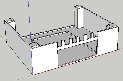
I wasn't too sure about having the USB power connectors go back through the case, as you might on a proper rack - but it would at least be sturdy. Other subsequent modules would match dimensions and become smaller or taller as required. Unfortunately, with 6 modules the height would be around 24cm. That's getting pretty tall - certainly taller than my PC case for sure. A few prints later and you can see that it's starting to take shape.
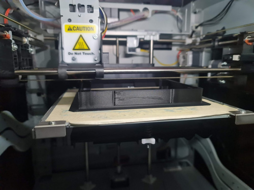
The first problem: the printing process was not great. These are some early prints after getting back into 3D Printing and many mistakes were made. I had assumed, for some reason, that I loaded the ABS Black spool in but it was PLA - I wouldn't find this out for some prints in. I had set the heat setting far too high for PLA - and just slightly low for ABS. The end result was that the molten plastic effectively scorched the printing tape underneath and caused a number of problems with the printing tape being embedded in the print itself. As I printed more, the quality seemed to get worse and the temperature of the garage certainly played a part in whether the first layer would stick to the tape.
Google and YouTube were fairly unhelpful - not because the content was wrong, but what I assumed to problem to be was wrong. I had followed advice to try Blue Painters Tape for adhesion, and this worked a little better. When I finally discovered that I had loaded the wrong spool in and I set the right temperature for PLA instead, it was far easier to replace the tape and so I continued a while with it.
I had only bought the one roll of PLA and further research would suggest and prove to be a far easier material to print with. But I'd bought several roles of ABS and needed to sort that one out. With some trial and error, I eventually settled on a Glass Square (200mm x 200m) with some Hair Spray to keep the ABS plastic down, and some Aluminium Foil inside the printer to help keep the heat in during printing (this had more of an impact than I thought it would - being in a Garage, it gets very cold in Victoria!). With some manual calibration of the Printer Bed, this turned out to be the best solution for both PLA and ABS. No more tape, super easy process to follow. If there was one thing I wish I knew before starting these prints again, is what 'bad' looks like.
There were a few other prints that were frankly rubbish. The design looked horrible and function definitely wasn't as good as it could be. So I continued browsing through Reddit and Thingiverse for more ideas. I saw a recent post about the Monty rack. This thing looks absolutely amazing albeit overbuilt for my purposes - but the concept is spot on. The case uses slotted extruded aluminium for the supports and 3D Printed rackmount inserts to mount everything in place. Prices in Australia for aluminium is not cheap though and frankly at the price just for the supports - I could certainly build something like this in a more visually attractive way, such as a wall mounted cluster.
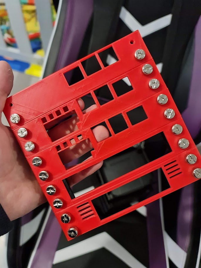
I ultimately decided not to do that (although it would have looked pretty cool with some water cooling and cables laid out on a board), and instead look at 3D Printing some supports. I would design a 2cm x 2cm design, with a trapezoid cut out to help give the screws themselves a little more plastic to help hold each face plate in place. Each 'RU' would effectively be 3cm high, and 15cm wide (11cm usable space, given the 2cm each side). The power supply will be mounted at the back, inside the rack 'square' and as such would create a nice little cube - around 15cmx16cm accounting for legs and a top (20cm if I decide to add handles).
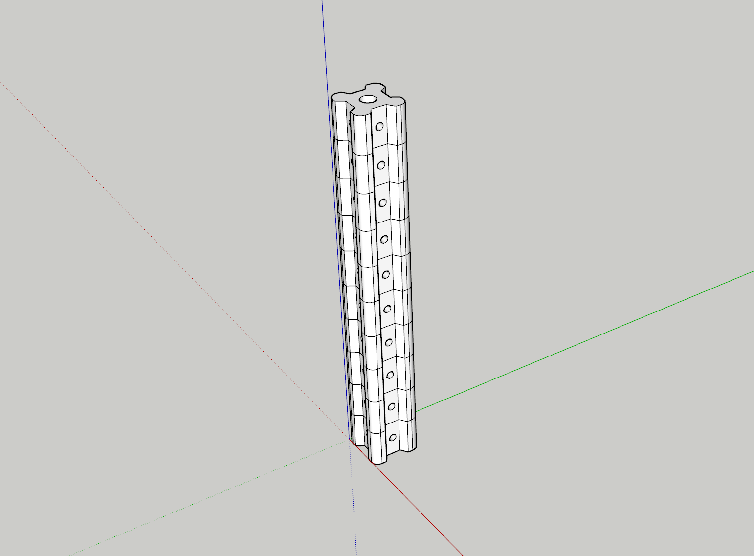
The holes are small enough to enable some self-tapping from some leftover M3 Thumb Screws I have from an old PC Repair kit to hold the face plates in place and each end will enable some standoffs to be glued in place to hold the top and bottom 'lids' in place. I chose Black for the Aluminium extrusions, Grey for the trays to hold components in place and Red for the face plates. The design would be somewhat reminiscent of 80's style electronics.
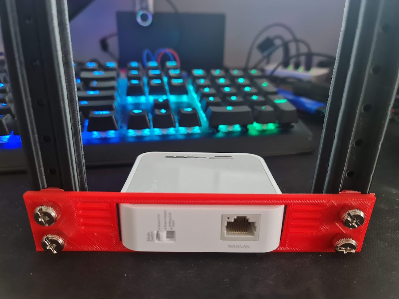
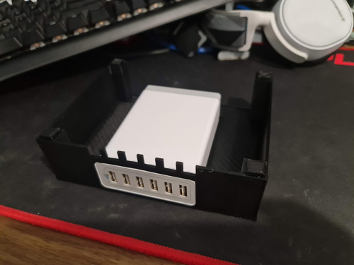
Ok - this thing looks about 1,000x better than the previous attempt and far better than I thought it would look. The holes are the right size for those M3 screws to grip without being overly troublesome (although if I were to do this all over again, I'd probably make the holes around 0.5mm smaller again) and the sizing for the first component is spot on. I'd just need to print a tray for this to sit in, some other faceplates and the other supports. If the Raspberry Pi now fits in the rack, along with the LED Lights / Buttons and OLED screen, we should be onto a winner.
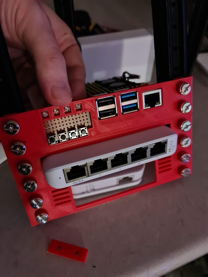
This Raspberry Pi faceplate probably took the most amount of time to get right - aligning the USB and Ethernet ports. I needed enough room to place the 4 x 3mm LEDs, 4 x Push Buttons and enough room for a 128x32 OLED Screen. The idea being that I can see what's running on each Raspberry Pi without necessarily logging in to see what's going on. If I need to reboot them, I can do it from the controller. The lights will help build and diagnose some GPIO projects and also enable the remainder of the rack to run a series of ARM-compatible containers. I would use a consistent approach for cooling via an Armour shell - if these things are running databases and Kubernetes, as well as powering a potential light show at the end of the year, then they're going to produce a fair bit of heat from each CPU.
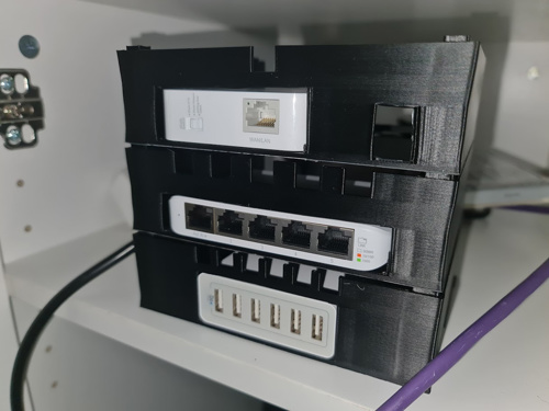
This leads up to the end of May when I thought I might only require a Raspberry Pi 2 as the Kubernetes master node. This has changed in design since then, but to give you an idea on what a full stack would look like (and when I noticed I didn't have an extra two thumb screws), I've placed the photo below.
At this stage, I'm pretty happy with the progress but still have a little bit more to do. For starters, I'll need to wire up a screen, buttons and do some programming before finalising the PCB for the slot. Secondly, I'll need to print all supports and the cover for top and bottom.
But that's where this post will end. Until next time!